My Flight Instruments
In the past 2.5 years, I've built a few different type of instruments for my flight deck. These either make use of TFT displays to draw steam gauge, digital and GPS instruments, or 7-segment number display and four-segment LCD displays for instruments like Radios and Transponder, or even purely mechanical ones like Keypads and Button/Switch Panels to turn settings on and off in the sim.
Steam Gauge Style Instruments
A series of "Steam Gauge" like instruments that use a 3.2" 320x240 TFT Display. They use a dual rotary encoder for interaction with the instrument. The outer bigger knob is used to switch between instrument screens, while the inner knob's and push button's functionality are specific to the selected screen, when applicable.
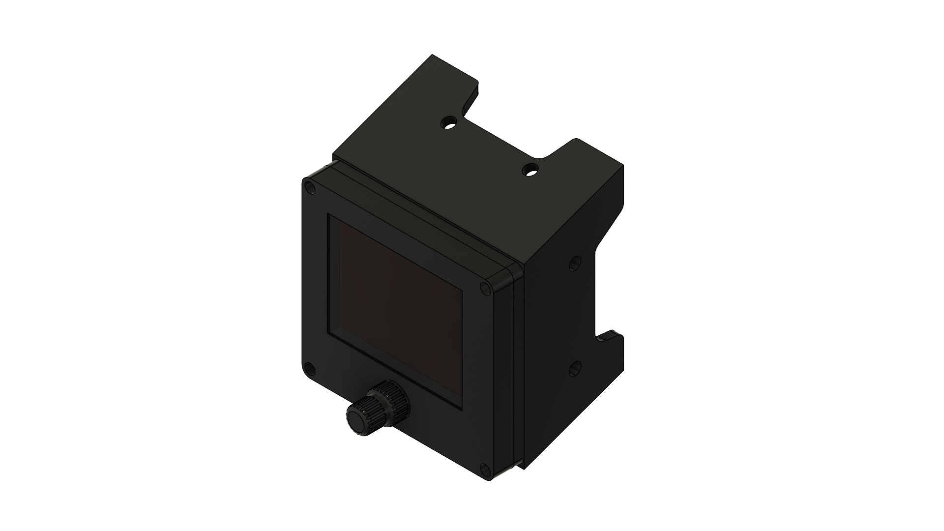
- Airspeed Indicator
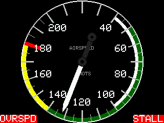
The Airspeed Indicator adjusts it's range based on the aircraft's redline airspeed and can display both overspeed and stall blinking alarms.
- Altimeter
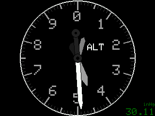
The Altimeter displays the current aircraft's indicated altitude and the barometric pressure setting in inches of mercury (inHg). You can use the knob to increase/decrease the barometric pressure setting, and by pressing the button it sends the 'reset' barometer to the sim so it sets it to the current in-game location's barometer setting.
- Ammeter
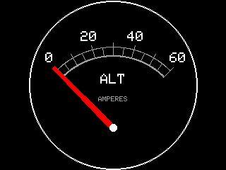
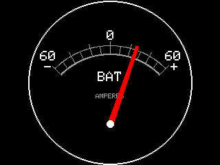
The Ammeter displays either the alternator's voltage or the main battery's actual voltage. You can press the button to switch between the two views.
- Attitude Indicator
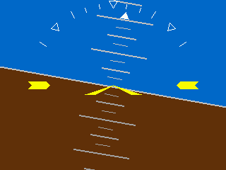
The Attitude Indicator is pretty simple that displays the attitude based on pitch and roll. You can use the knob to adjust the yellow markers as you would do on a steam gauge attitude indicator to set the horizon.
- Clock & Timer
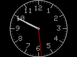
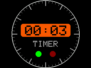
There are two modes for the clock instrument. The first just displays an analog clock with the current time, which relies on the computer's clock. The second mode is used as a start/stop/reset timer.
- Flaps and Trim
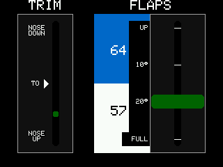
The Trim part of this instrument shows the position of the aircraft's elevator trim. The Flaps part shows the current flaps position and shows the current aircraft's VS0 and VS1 design values. The number of flap notches changes based on the aircraft. These were inspired in the Cessna's controls.
- Fuel Gauges
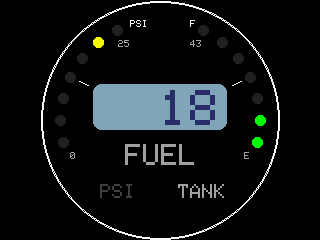
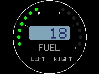
The Fuel Gauges are one of the remaining instruments that were designed inspired by general aviation gauges that combine LEDs to represent levels and an LCD display to show a value. I originally designed them like this when I was using an Arduino and had to manually redraw sections of the screen because of the lack of memory required to do dual buffering.
The first gauge represent the main fuel pressure and the combined total fuel across the main two tanks. Pressing the button toggles between displaying the numeric total fuel quantity or the fuel pressure.
The second gauge displays each tank's individual fuel quantity and depending on the fuel selector position in the aircraft, it shows the left, the right, or combined values in the display.
- Heading indicator
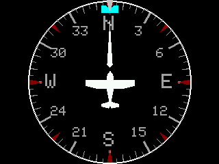
The Heading Indicator displays the gyro driven heading. It includes a heading bug that can be controlled using the knob and can be synced to the current heading by pressing the button.
- Horizontal Situation Indicator
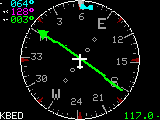
The Horizontal Situation Indicator is inspired by Garmin's and Aspen's digital HSI. Besides showing the current heading like the heading indicator, it shows the localizer needle, and the next waypoint's name and distance. When in VOR mode, the needle, course (CRS) and distance are displayed in green. When in GPS, they are magenta and CRS is replaced by the desired track (DTK). Similar to the Heading Indicator, the knob is used to control the heading bug, with the addition that when the button is pressed, the sync event is sent to the sim's autopilot.
- Landing Gear
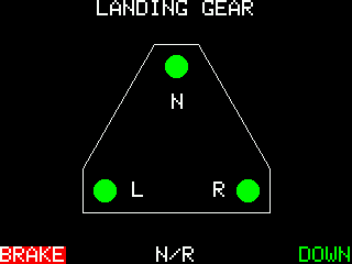
A simple Landing Gear position indicator. Green means down, blinking yellow is transition, red is up. It also shows a label on the bottom that displays messages like "N/R" for non-retractable gear, SKIDS, SKIIS, based on the aircraft being flown. It also shows BRAKE when the parking brake is set.
- Magnetic Compass
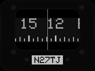
A simple Magnetic Compass that even shows the label with the aircraft's tail number.
- Manifold Pressure
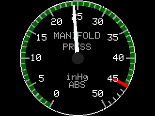
A typical Manifold Pressure indicator in inches of mercury (inHg).
- Oil Gauge
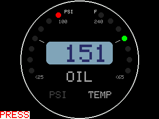
An Oil Gauge that displays both the main engine's oil temperature and pressure. It can also display alarms like PRESS and TEMP when the values are too high or low.
- Primary Flight Display
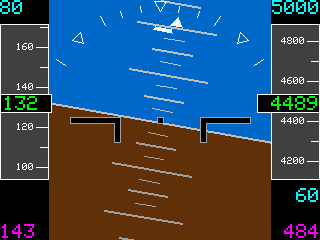
Similar to the HSI, this was inspired by Garmin's and Aspen's PFDs. It shows the attitude based on pitch and roll, the current altitude and airspeed tapes that scroll up and down, with the current value in green, the autopilot selected values for altitude, airspeed and vertical speed in cyan, and ground speed and actual climb speed in magenta.
The knob is used to adjust the autopilot selected values. By pressing the button once, you enter edit mode for autopilot selected altitude, a second press for the autopilot selected airspeed and a third for the autopilot selected climb rate. While in edit mode, the field being modified will blink and you can use knob to increase/decrease the value. If no inputs are done after 10 seconds, the current value will be set and the edit mode will end. A fourth button push exits edit mode.
- Tachometer
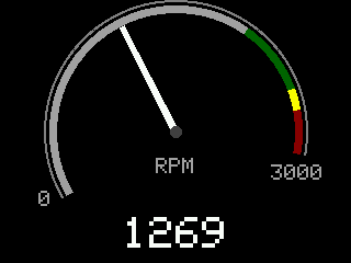
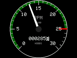
There are two types of tachometer gauges. A digital one like the one you will find in a Garmin G1000 and an analog one inspired by the one you would find in a Piper Warrior. By pressing the button, you can toggle between analog and digital mode. While in analog mode, you can rotate the knob to toggle displaying between Hobbs or Tachometer value.
- Turn Coordinator
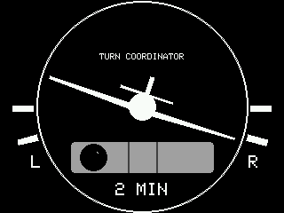
A simple Turn Coordinator that shows the bank angle and the position of the ball, with the corresponding standard rate of turn markers.
- Vertical Speed Indicator
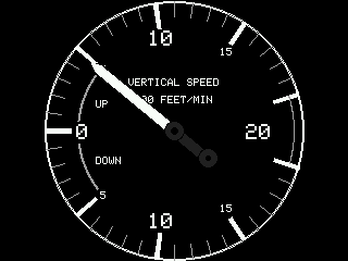
A simple Vertical Speed Indicator in 100's of feet per minute.
- VOR
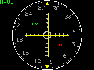
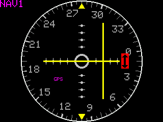
The VORs can be set to get it's data from NAV1 or NAV2. Depending on what is selected in the sim's NAV radio, it will either display GPS or VLOC mode, magenta and green respectively. If a signal is not present for horizontal or vertical guidance, a red arrow will be shown the same way you would find in the GA VORs. By turning the knob you can turn the numbers the same way you do when turning the OBS knob on the instrument. The needles move according to the deviation.
- Weather Briefing
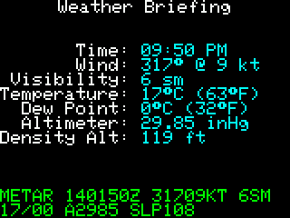
A text based instrument that displays the current weather conditions at the aircraft's current position in the sim. It shows it both in human-readable format and METAR format. This is the only instrument that is only updated once a minute to be a bit more realistic.
Magnetic Compass
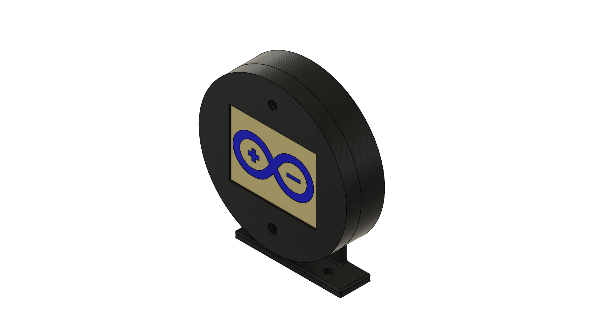
For the Magnetic Compass, I designed a different enclosure that uses an Adafruit 2.8" 320x240 TFT screen instead of the 3.2" TFT screen that the rest of the instruments use. Since it's only purpose is to displays the magnetic compass, it has no rotary encoder. It runs the exact same code, except I turn on a build flag to just have the magnetic compass on it.
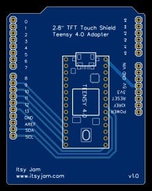
This 2.8" screen comes as an Arduino Shield that is mounted on top of an Arduino UNO. Since I'm now using Teensy for all my instruments, after figuring out the minimum wiring needed to connect it to a Teensy, I decided to start looking into PCB design and designed a board the size of an Arduino so I could mount the Teensy on and rewire the header pins to the Teensy. This was the design:
GNS430 Style GPS
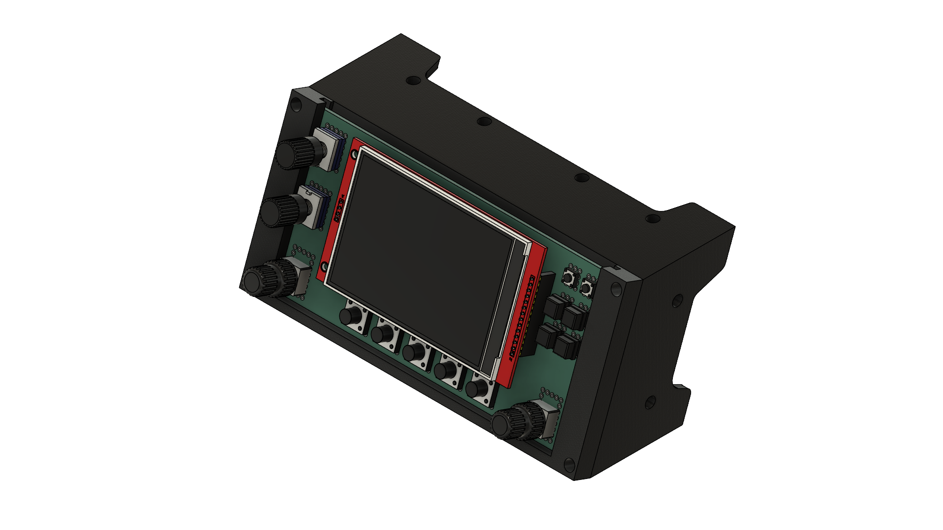
A Garmin like GNS430 like GPS using a 4.0" 480x320 TFT Display. It displays the COM and NAV frequencies for the selected radio (1 or 2), which can be set by a jumper.
- NAV Page 1
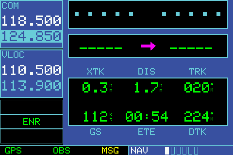
NAV Page 1 shows the flight plan's next waypoint information such as Desired Track, Distance, Estimated Time Enroute, along the current Track and Ground Speed.
- NAV Page 2
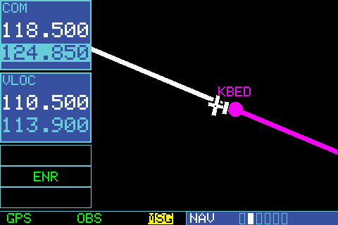
NAV Page 2 displays the aerial view map with the flight plan and waypoints.
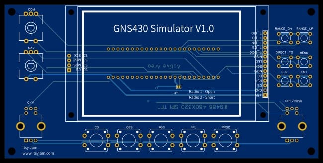
Note that the GPS is still a work in progress. Rest of the pages haven't been implemented yet but this is the minimum needed for navigation. Also, the faceplate is not finished since at this point I was using a perfboard to solder everything and after mounting all the components and soldering the screen and all the button and encoder's grounds, I realized I still had to solder 27 signal lines for each (and I'm building 2), and after a fun experience designing a PCB for the Magnetic Compass, I started designing one for this too. Right now it's looking like this:
Radio*
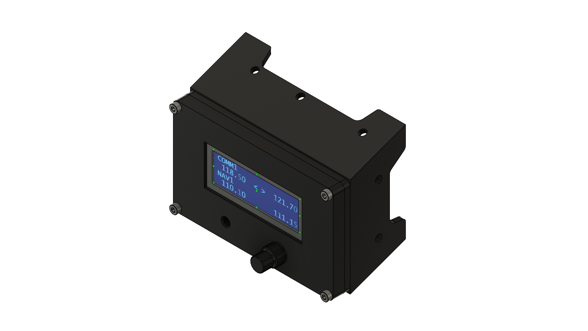
The Radio uses a 4-segment LCD display to show the active/standby frequencies for the COM and NAV radios for either Radio 1 or 2. The radio can be set via a jumper on the back. Pressing the rotary encoder button toggles from selecting COM or NAV, and pressing on the pushbutton swaps the frequencies. Rotating the inner and outer knobs changes either part of the frequency like typical aviation radios. Upon update, it sends the new frequencies to the sim.
* I have mostly retired this instrument since the GNS430's I'm building will incorporate the same radio setting functionality built in the GNS430's
Transponder
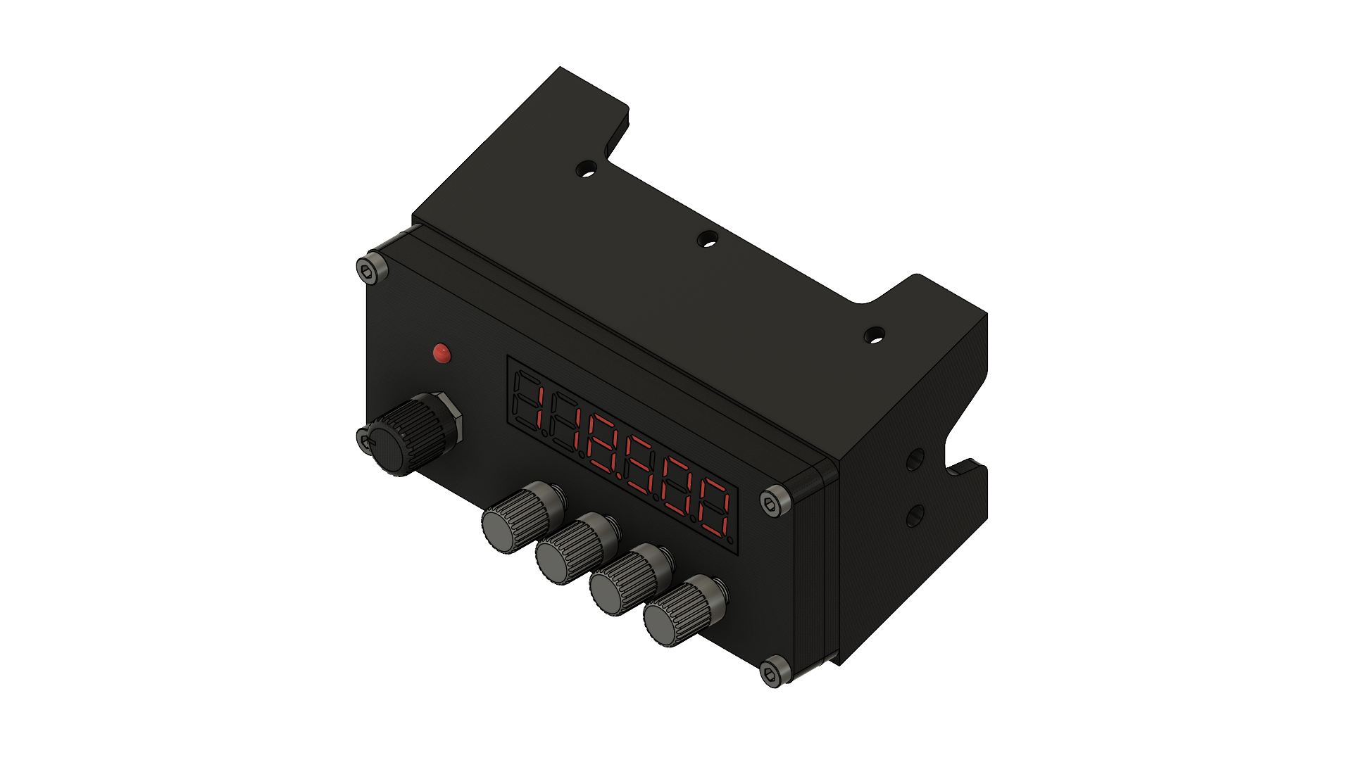
This is the original version of my transponder that uses a 6-digit 7-segment display to show the transponder code. It uses each rotary encoder to increase or decrease the corresponding digit's value. When I say that it's the original version, is because I started converting this to use push buttons like more modern transponders and while I soldered everything and rewrote the code, I never finished designing the new faceplate and sitting in a drawer somewhere 😄
Keypad
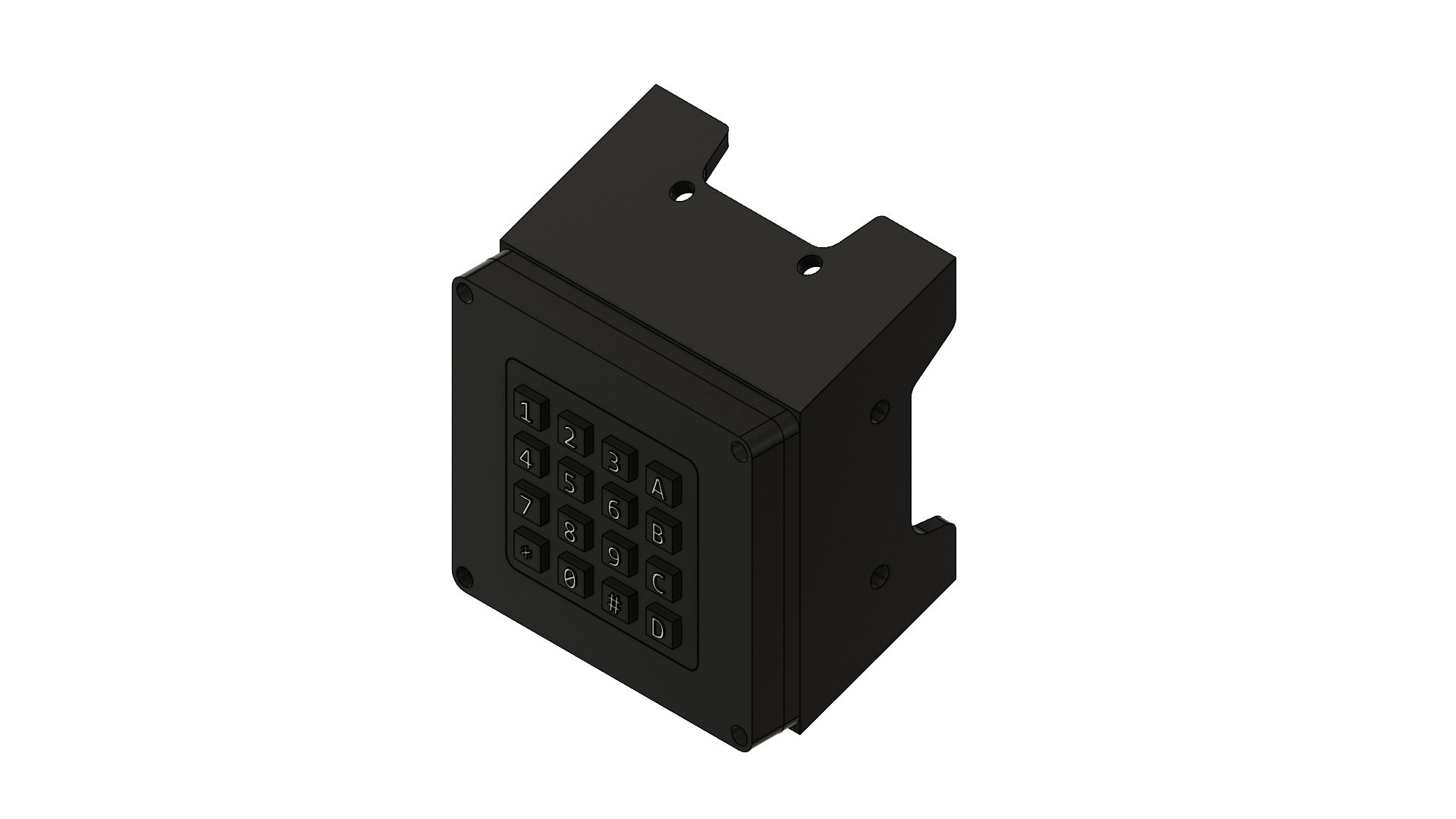
A simple keypad that sends the corresponding keys to the computer it's connected to as if it was a keyboard. I use this to map the keys to the sim, so I can for example use 1-9 to reply to the ATC window, and pop the ATC and Map windows or open the pause menu and stuff like that. It's built to fit in the same 1U bracket the Steam Gauge instrument is mounted on.
For details on how I implemented this one, check out the A Simple Keypad blog post.
Garmin G1000 screen
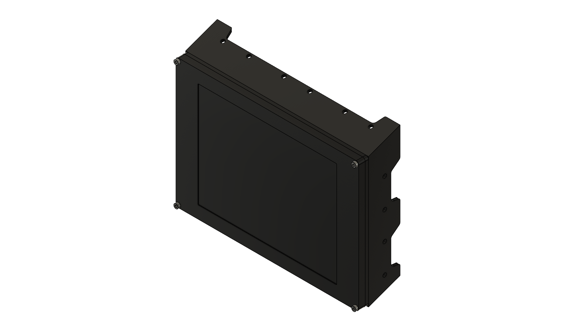
This one is a little bit different than the other displays I built. For this the idea was to make use of the simulator's ability to pop out an instrument's screen and put it on another monitor. I bought two 10.4" 1024x786 IPS HDMI screens from Amazon, and designed an enclosure to mount it along the rest of the instruments.
You can find the one I bought here:
https://www.amazon.com/dp/B07R3RZC4F?ref=ppx_yo2ov_dt_b_fed_asin_title&th=1
While at this point I'm only using them as a display, version 2 of this will include some rotary encoders and push buttons to be able to interact with the simulator's G1000. At this point, most of the functionality I need I already have it implemented in the PDF and HSI instruments, but to interact with the G1000 NXi itself, I need to write a WASM module and still learning how to do that 😄
Honorable Mentions
While this looks like an extensive list of instruments and controls, there are a few others that, while functional at the moment, I'm not using them anymore for different reasons and I repurposed the parts of some of them.
For example, before getting my Honeycomb Bravo Quadrant, I had a Saitek Throttle Quadrant (now Logitech) which didn't include a Trim Wheel like the Bravo. I ended up building an addon for the quadrant that made use of two rotary encoders, one mounted on a 3D printed elevator trim wheel and the other one on the front for controlling the rudder trim. It used an Arduino Leonardo and the Joystick.h library I used in the Arduino Joystick Emulation blog post to call setThrottle() and setRudder() analog axes to control the elevator and rudder trim in the sim.
Another example is the original flight instrument I built using the 2.8" TFT screen, was similar to the 3.2" ones but when I looked at the final product, there was more than enough room for a bigger screen and ended up repurposing the 2.8" for the Magnetic Compass.
All the instruments are controlled by my Instrument Panel Plugin WPF app, which I might showcase on a future blog post.

All the instrument screenshots are taken directly from the Teensy's memory, sent as an RGB byte array through the Serial connection to the app running on the PC and then reconstructed and rendered on a popup window with the option to save as a PNG. I will probably cover this at some point in a future blog post.

All the 3D modeling is done in Autodesk Fusion 360 that gives you the option to Capture Image to get a nice PNG, even lets you do a transparent background.
I used EasyEDA to design the PCBs, which then I ordered from JLCPCB